Thursday, June 28, 2007

Step-by-Step Guide for Setting Up a PPTP-based Site-to-Site VPN Connection in a Test Lab

From MS

Step-by-Step Guide for Setting Up a PPTP-based Site-to-Site VPN Connection in a Test Lab

This guide provides an example with detailed information about how you can use five computers in a test lab environment to configure and test a Point-to-Point Tunneling Protocol (PPTP)-based site-to-site VPN connection using any 32-bit version of the Microsoft® Windows Server™ 2003 operating system with Service Pack 1 (SP1) as well as the Microsoft Windows® XP Professional operating system with Service Pack 2 (SP2).You can use this example deployment to learn about Windows Server 2003 with SP1 site-to-site VPN functionality before you deploy a site-to-site VPN connection in a production environment. This test lab configuration simulates a deployment of a PPTP-based site-to-site VPN connection between the Seattle and New York offices of an organization

Note
The following instructions are for configuring a test lab using a minimum number of computers. Individual computers are needed to separate the services provided on the network and to clearly show the functionality. This configuration is designed to reflect neither best practices nor a recommended configuration for a production network. The configuration, including IP addresses and all other configuration parameters, is designed to work only on a separate test lab network.

Setting Up the Test Lab

The infrastructure for a PPTP-based site-to-site VPN deployment test lab network consists of five stand-alone computers performing the roles shown in Table 1. Each computer is part of a workgroup. None of the computers are joined to a domain. In this test lab scenario, Windows Firewall is installed and turned-on automatically on the client computers running Windows XP Professional with SP2. You will configure a Windows Firewall exception on CLIENT1, allowing communication between the two client computers. On the three computers with Windows Server 2003 with SP1, Standard Edition, Windows Firewall is automatically installed, but it is not turned-on by default. On these computers, Windows Firewall will remain turned-off. In addition, the Windows Firewall/Internet Connection Sharing (ICS) service should be disabled on each of these computers.

In addition to these five computers, the test lab also contains four hubs (or Layer 2 switches):
· A hub that connects the Seattle office (CLIENT1) to the answering router (ROUTER1).
· A hub that connects the New York office (CLIENT2) to the calling router (ROUTER2).
· A hub that connects the answering router (ROUTER1) to the Internet router (INTERNET).·
A hub that connects the calling router (ROUTER2) to the Internet router (INTERNET).

Note
Because there are only two computers on each subnet, the hubs can be replaced by Ethernet crossover cables.The configuration of this test lab is shown in the following figure:

Configure your test lab by performing the following tasks:
1. Configure the client computers in the Seattle and New York offices.
2. Configure the computers performing as the answering and calling routers.
3. Configure the computer performing as the Internet router.
CLIENT1 is a client on the Seattle office subnet, running Windows XP Professional with SP2.
Configure TCP/IP properties
1. Open Network Connections, right-click the network connection you want to configure, and then click Properties.
2. On the General tab, click Internet Protocol (TCP/IP), and then click Properties.
3. Click Use the following IP address, type 172.16.4.3 for the IP address, type 255.255.255.0 for the Subnet mask, and then type 172.16.4.1 for the Default gateway.
Installing Windows XP Professional with SP2 turns on Windows Firewall by default. You will need to configure port exceptions on the firewall allowing for communication between CLIENT1 and CLIENT2.
Configure Windows Firewall on CLIENT1
1. Click Start, point to Control Panel, and then click Security Center.
2. Click Windows Firewall, and then in the Windows Firewall dialog box, click the Advanced tab.
3. Click Settings for ICMP, and then click Allow incoming echo request.
4. Click OK twice to close Windows Firewall.
CLIENT2 is a client on the New York office subnet, running Windows XP Professional with SP2. Installing Windows XP Professional with SP2 turns on Windows Firewall by default. However, because CLIENT2's only role is as a calling computer, Windows Firewall does not need to be enabled with any exceptions. Leave the default Windows Firewall settings on CLIENT2.
Configure TCP/IP properties
1. Open Network Connections, right-click the network connection you want to configure, and then click Properties.
2. On the General tab, click Internet Protocol (TCP/IP), and then click Properties.
3. Click Use the following IP address, and then type 172.16.56.3 for the IP address, type 255.255.255.0 for the Subnet mask, and then type 172.16.56.1 for the Default gateway.
This section describes the setup for the routers in the test lab. For information about configuring routing and remote access for the answering router (ROUTER1) and the calling router (ROUTER2), see “Configuring a PPTP-based Site-to-Site VPN Connection” in this guide.

ROUTER1 is a computer on the Seattle office subnet, running Windows Server 2003 with SP1, Standard Edition. ROUTER1 is acting as the answering router.
Configure TCP/IP properties
1. Open Network Connections, right-click the network connection you want to configure, and then click Properties.
2. On the General tab, click Internet Protocol (TCP/IP), and then click Properties.
3. Configure the IP address and subnet mask with the following values:
a. On the To the Internet interface, type 10.1.0.2 for the IP address, type 255.255.0.0 for the Subnet mask, and then type 10.1.0.1 for the Default gateway.
b. On the To the Seattle intranet interface, type 172.16.4.1 for the IP address, type 255.255.255.0 for the Subnet mask. Leave the Default gateway clear.
Windows Firewall and Routing and Remote Access cannot run simultaneously on VPN1. If Windows Firewall is turned on, you will need to disable it. If the Windows Firewall/Internet Connection Sharing (ICS) service has started or is set to automatic before configuring Routing and Remote Access, you must disable it.
Disable the Windows Firewall/Internet Connection Sharing (ICS) service
1. Click Administrative Tools, and then click Services.
2. In the Services details pane, right-click Windows Firewall/Internet Connection Sharing (ICS) service, and then click Properties.
3. If the service Startup Type is either Automatic or Manual, change it to Disabled.
4. Click OK to close the Windows Firewall/Internet Connection Sharing (ICS) dialog box, and then close the Services page.
ROUTER2
ROUTER2 is a computer on the New York office subnet, running Windows Server 2003 with SP1, Standard Edition. ROUTER2 is acting as the calling router.
Configure TCP/IP properties
1. Open Network Connections, right-click the network connection you want to configure, and then click Properties.
2. On the General tab, click Internet Protocol (TCP/IP), and then click Properties.
3. Configure the IP address and subnet mask with the following values:
a. On the To the Internet interface, type 10.2.0.2 for the IP address, type 255.255.0.0 for the Subnet mask, and then type 10.2.0.1 for the Default gateway.
b. On the To the Seattle intranet interface, type 172.16.56.1 for the IP address, type 255.255.255.0 for the Subnet mask. Leave the Default gateway empty.
As with ROUTER1, you must turn off Windows Firewall on ROUTER2 and disable the Windows Firewall/ICS service.
Disable the Windows Firewall/Internet Connection Sharing (ICS) service
1. Click Administrative Tools, and then click Services.
2. In the Services details pane, right-click Windows Firewall/Internet Connection Sharing (ICS) service, and then click Properties.
3. If the service Startup Type is either Automatic or Manual, change it to Disabled.
4. Click OK to close the Windows Firewall/Internet Connection Sharing (ICS) dialog box, and then close the Services page.
Configuration for the Internet Router
INTERNET is a computer running Windows Server 2003 with SP1, Standard Edition.
Configure TCP/IP properties
1. Open Network Connections, right-click the network connection you want to configure, and then click Properties.
2. On the General tab, click Internet Protocol (TCP/IP), and then click Properties.
3. Configure the IP address and subnet mask with the following values:
a. On the To Router1 interface, type 10.1.0.1 for the IP address, and then type 255.255.0.0 for the Subnet mask.
b. On the To Router2 interface, type 10.2.0.1 for the IP address, and then type 255.255.0.0 for the Subnet mask.
4. Click Administrative Tools, and then click Routing and Remote Access to open the Routing and Remote Access Microsoft Management Console (MMC) snap-in.
5. In the Routing and Remote Access snap-in, right-click INTERNET (local) in the console tree, and then click Configure and Enable Routing and Remote Access.
6. The Routing and Remote Access Server Setup Wizard opens. Click Next.
7. On the Configuration page, select Custom configuration, as shown in the following figure.

8. Click Next. On the Custom Configuration page, select LAN routing, as shown in the following figure.

9. Click Next. On the Completing the Routing and Remote Access Server Setup page, click Finish, and then click Yes to start the service.

8. Click Next. On the Custom Configuration page, select LAN routing, as shown in the following figure.


9. Click Next. On the Completing the Routing and Remote Access Server Setup page, click Finish, and then click Yes to start the service.
Make sure that Windows Firewall is turned off and that the Windows Firewall/Internet Connection Sharing (ICS) service is disabled.
Disable the Windows Firewall/Internet Connection Sharing (ICS) service
1. Click Administrative Tools, and then click Services.
2. In the Services details pane, right-click Windows Firewall/Internet Connection Sharing (ICS) service, and then click Properties.
3. If the service Startup Type is either Automatic or Manual, change it to Disabled.
4. Click OK to close the Windows Firewall/Internet Connection Sharing (ICS) dialog box, and then close the Services page.

Verify the routing infrastructure
1. On ROUTER1, ping the IP address 10.2.0.2. This should be successful.
2. On CLIENT2, ping the IP address 172.16.4.3. This should be unsuccessful because CLIENT1 cannot be reached by CLIENT2 across the simulated Internet until the site-to-site VPN connection is created.
Configuring a PPTP-based Site-to-Site VPN Connection
To create a PPTP-based VPN connection, perform the following tasks:
1. Configure VPN on the answering router.
2. Configure the demand-dial interface on the answering router.
3. Configure VPN on the calling router.
4. Configure the demand-dial interface on the calling router.
5. Confirm remote access policy configuration on the answering and calling routers.
6. Initiate the VPN connection.
7. Test the VPN connection.

Configure VPN on the answering router (ROUTER1)
1. On ROUTER1, click Administrative Tools, and then click Routing and Remote Access.
2. In Routing and Remote Access, right-click ROUTER1 (local) in the console tree, and then click Configure and Enable Routing and Remote Access.
3. The Routing and Remote Access Server Setup Wizard appears. Click Next.
4. On the Configuration page, select Remote access (dial-up or VPN), as shown in the following figure.


5. Click Next. On the Remote Access page, select VPN, as shown in the following figure.


6. Click Next. On the VPN Connection page, select To the Internet, and then verify that the Enable security on the selected interface by setting up static packet filters check box is selected, as shown in the following figure


7. Click Next. On the IP Address Assignment page, select From a specified range of addresses, as shown in the following figure


8. Click Next. On the Address Range Assignment page, click New, as shown in the following figure


9. In the New Address Range dialog box, do the following:
a. In the Start IP address box, type 172.16.100.1.
b. In the End IP address box, type 172.16.100.2.
c. In the Number of Addresses box, accept the displayed value of 2, as shown in the following figure.


10. Click OK. On the Address Range Assignment page, click Next.
11. On the Managing Multiple Remote Access Servers page, select No, use Routing and Remote Access to authenticate connection requests, as shown in the following figure.


12. Click Next. On the Completing the Routing and Remote Access Server Setup page, click Finish.13. Click OK to close the message box prompting you to configure the DHCP Relay Agent. For this scenario the DHCP Relay Agent will not be configured.

Configure the demand-dial interface on the answering router (ROUTER1)
1. In the Routing and Remote Access snap-in, expand ROUTER1, and then right-click Network Interfaces.
2. Click New Demand-dial Interface to open the Demand-Dial Interface Wizard, and then click Next.
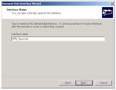
3. On the Interface Name page, type VPN_NewYork, as shown in the following figure. The interface name must match the user account name of the calling router.


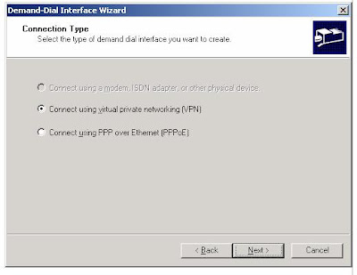
4. Click Next. On the Connection Type page, select Connect using virtual private networking (VPN), as shown in the following figure.


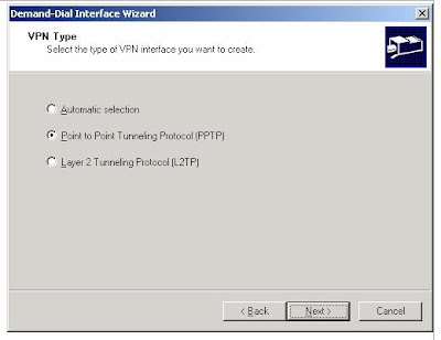
5. Click Next. On the VPN Type page, select Point-to-Point Tunneling Protocol (PPTP), as shown in the following figure


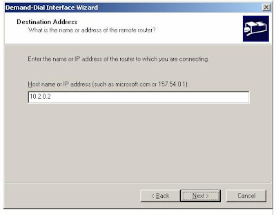
6. Click Next. On the Destination Address page, type 10.2.0.2 in the Host name or IP address box, as shown in the following figure.


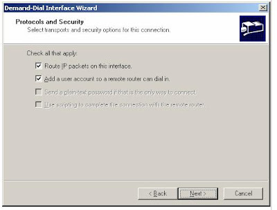
7. Click Next. On the Protocols and Security page, do the following:
a. Select Route IP packets on this interface.
b. Select Add a user account so a remote router can dial in, as shown in the following figure.


8. Click Next. On the Static Routes for Remote Networks page, click Add, as shown in the following figure.


9. In the Static Route dialog box, do the following:
a. In the Destination box, type 172.16.56.0.
b. In the Network Mask box, type 255.255.255.0.
c. In the Metric box, accept the displayed value 1, as shown in the following figure.


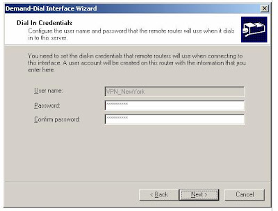
10. Click OK. On the Static Routes for Remote Networks page, click Next.11. On the Dial In Credentials page, type a password for the VPN_NewYork user account, and then retype the password in the Confirm password box. The User name box is automatically populated with the value VPN_NewYork


12. Click Next. On the Dial Out Credentials page, do the following:
a. In the User name box, type VPN_Seattle.
b. In the Domain box, type ROUTER2.
c. In the Password box, type a password for the VPN_Seattle user account.
d. In the Confirm password box, retype the password for the VPN_Seattle user account, as shown in the following figure.


13. Click Next. On the last Demand-Dial Interface Wizard page, click Finish.
14. Click OK to close the message box prompting you to configure the DHCP Relay Agent. For this scenario the DHCP Relay Agent will not be configured.
Configure VPN on the calling router (ROUTER2)
1. On ROUTER2, click Administrative Tools, and then click Routing and Remote Access.
2. In Routing and Remote Access, right-click ROUTER2 (local) in the console tree, and then click Configure and Enable Routing and Remote Access.
3. The Routing and Remote Access Server Setup Wizard appears. Click Next.
4. On the Configuration page, select Remote access (dial-up or VPN), and then click Next.
5. On the Remote Access page, select VPN, and then click Next.
6. On the VPN Connection page, select To the Internet, verify that the Enable security on the selected interface by setting up static packet filters check box is selected, and then click Next.
7. On the IP Address Assignment page, select From a specified range of addresses, click Next, and then on the Address Range Assignment page, click New.
8. In the New Address Range dialog box, do the following:
a. In the Start IP address box: type 172.56.200.1.
b. In the End IP address box, type 172.56.200.2.
c. In the Number of Addresses box, accept the displayed value of 2, and then click OK.
9. On the Address Range Assignment page, click Next.
10. On the Managing Multiple Remote Access Servers page, select No, use Routing and Remote Access to authenticate connection requests. Click Next.
11. On the Completing the Routing and Remote Access Server Setup page, click Finish.
12. Click OK to close the message box prompting you to configure the DHCP Relay Agent.
Configure the demand-dial interface on the calling router (ROUTER2)
1. In the Routing and Remote Access snap-in, expand ROUTER2 (local), and then right-click Network Interfaces.
2. Click New Demand-dial Interface to open the Demand-dial Interface Wizard. To complete the Demand-Dial Interface Wizard, click Next.
3. On the Interface Name page, type VPN_Seattle. The interface name must match the user account name of the answering router. Click Next.
4. On the Connection Type page, select Connect using virtual private networking (VPN). Click Next.
5. On the VPN Type page, select Point-to-Point Tunneling Protocol (PPTP). Click Next.
6. On the Destination Address page, type 10.1.0.2, and then click Next.
7. On the Protocols and Security page, do the following:
a. Select Route IP packets on this interface.
b. Select Add a user account so a remote router can dial in, and then click Next.
8. On the Static Routes for Remote Networks page, click Add.
9. In the Static Route dialog box, do the following:
a. In the Destination box, type 172.16.4.0.
b. In the Network Mask box, type 255.255.255.0.
c. In the Metric box, accept the displayed value 1, and then click OK.
10. On the Static Routes for Remote Networks page, click Next.
11. On the Dial In Credentials page, type the password for the VPN_Seattle user account, and then retype the password in the Confirm password box. The User name box is pre-populated with the value VPN_Seattle. Click Next.
12. On the Dial Out Credentials page, do the following:
a. In the User name box, type VPN_NewYork.
b. In the Domain box, type ROUTER1.
c. In the Password box, type the password for the VPN_NewYork user account created on ROUTER1.
d. In the Confirm password box, retype the password for the VPN_NewYork user account, and then click Next.
13. On the last Demand-Dial Interface Wizard page, click Finish
Confirm the remote access policy configuration on the answering and calling routers
1. On ROUTER2, in Routing and Remote Access, click Remote Access Policies.
2. In the details pane, right-click Connections to Microsoft Routing and Remote Access server, and then click Properties.
3. On the Settings tab, select Grant remote access permission, and then click OK to save changes.4. Repeat steps 1 through 3 on ROUTER1.
Initiate the VPN connection by performing the following steps on ROUTER2.
Initiate the VPN connection
1. On ROUTER2, in the console tree of the Routing and Remote Access snap-in, click Network Interfaces.
2. In the details pane, right-click VPN_Seattle, and then click Connect.
3. Confirm that the connection state of VPN_Seattle is connected.
Test the VPN connection
1. On CLIENT2, at the command prompt, type ping 172.16.4.3.
This is the IP address for CLIENT1. Pinging CLIENT1 from CLIENT2 will test whether the Seattle subnet is now reachable.
2. To confirm that the packets crossed the VPN connection, at the command prompt, type tracert 172.16.4.3. Note that you must use the IP address of CLIENT1, rather than its computer name, because a DNS server is not configured in this test lab scenario.
Results that are similar to the following indicate that the connection is working.
Tracing route to 172.16.4.3 over a maximum of 30 hops:
1 <1 ms <1 ms <1 ms [172.16.56.1]
2 1 ms <1 ms <1 ms [172.56.200.2]
3 1 ms 1 ms 1 ms [172.16.4.3]
Trace complete.

Note
172.16.56.1 is the IP address of the ROUTER2 interface that connects to the New York intranet. 172.56.200.2 is the IP address that ROUTER2 assigned to ROUTER1. The presence of this IP address in the Tracert output indicates that packets are moving across the site-to-site VPN connection. 172.16.4.3 is the IP address of CLIENT1.


Monday, June 25, 2007

How to receive MCP from MS

From NhatNghe web site
Microsoft Certified Professional Programs
If U pass the mcp, U'll receive 2 mail from MS, The first mail tell U MCP ID , the second mail tell U ACCESS CODE.
Email 1:
Microsoft Certified Professional Programs (mswwprog@microsoft.com)
To: Your Email
Subject: Access Your MCP Benefits: Part 1 (Action Required)

Congratulations on becoming a Microsoft Certified Professional!As you Know,earning a Microsoft Certification is an investment in your technology skills and career,and we look forward to helping you succeed

FOLLOW THESE STEPS TO ACCESS YOUR MCP MEMBER BENEFITS:

1.SAVE THIS E-MAIL OR RECORD YOUR MCP ID.Your personal MCP ID number grants you access to the MCP member site where youwill find MCP only information, your transcript, logos, and other benefits. In addition,you 'll need to register for future exams with your MCP ID to make sure your transcript iskept up to date
-------------------------------------------------------------------------
YOUR MCP ID IS:123456
-------------------------------------------------------------------------

2.ASSOCIATE YOUR WINDOWS LIVE ID TO YOUR MCP ID.Follow these instructions (http://www.microsoft.com/learning/mcp/passport/instructions.asp) to associate yourWindows Live ID (formerly Passport Network account) with your MCP ID. This processis called ômigrationö and will allow you access to the MCP site and your benefits

3.ACCESS THE MCP PRIVATE SITE WITHIN 21 DAYS.To access the site, you will need your ômigratedö Windows Live ID and a temporaryaccess CODE that you 'll receive from Microsoft in a separate ôPart 2ö e-mail. If you do notreceive "Part 2" within 24 hours of receiving this e-mail, contact your Regional ServiceCenter (http://www.microsoft.com/learning/support/worldsites.asp).

4.CONFIRM YOUR PROFILE INFORMATION.After accessing the MCP site, you 'll want to confirm your profile to ensure you get your benefits, offers, and program news.

5.REQUEST YOUR MEMBER KIT.Welcome kits are not shipped automatically. After accessing the MCP site,you 'll need to submit a request for your kit from the MCP site.

6.EXPLORE THE COMMUNITY!Start to get familiar with the resources now available to you as an MCP fromhttp://www.microsoft.com/learning/mcpwelcome. Welcome to Microsoft Certification!Thank you,The Microsoft Certification Program Team,
************************************************************************
Please do not reply to this e-mail message. If you have comments or questions or needhelp, please contact your Regional Service Center:http://www.microsoft.com/learning/support/worldsites.asp

Email 2:
Microsoft Certified Professional Programs (mswwprog@microsoft.com)
To: Your Email
Subject: Access Your MCP Benefits: Part 2 (Action Required)

Again, congratulations on your new Microsoft Certification.

This is the second of two e-mails to help you access your benefits as part of the MCP community.

FOLLOW THESE STEPS TO ACCESS YOUR MCP MEMBER BENEFITS:

1.YOU SHOULD HAVE RECEIVED YOUR MCP ID IN A PREVIOUS E-MAIL.If you did not receive a "Part 1" e-mail from Microsoft in the last 24 hours, please contact contact your Regional Service Center (RSC) (http://www.microsoft.com/learning/support/worldsites.asp).

2.ASSOCIATE YOUR WINDOWS LIVE ID TO YOUR MCP ID.If you have not already done so, follow these instructions (http://www.microsoft.com/learning/mcp/passport/instructions.asp) to associate your Windows Live ID(formerly Passport Network account) with your MCP ID. This process is called "migration".

3.ACCESS THE MCP PRIVATE SITE WITHIN 21 DAYS.Log-in to the MCP site (https://mcp.microsoft.com/mcp/Default.aspx) by using your "migrated" Windows Live ID and temporary access CODE, below. Microsofttakes the security of your information very seriously, so this CODE will only be active for 21 days. If your CODE is no longer valid, please contact your RSC.
---------------------------------------------------------------------------------
YOUR TEMPORARY ACCESS CODE IS: FC171460-C4C6-4707-9954-AAA6DEB9701C
---------------------------------------------------------------------------------

4.CONFIRM YOUR PROFILE INFORMATION.From https://mcp.microsoft.com/mcp/Default.aspx, select VIEW MY... PROFILE from the left navigation and confirm that your e-mail address and profile is correct so we can reach you with benefits, offers, and program news.

5.REQUEST YOUR MEMBER KIT.Welcome kits are not shipped automatically. Visit https://mcp.microsoft.com/mcp/Default.aspx, select PROGRAM BENEFITS, then MEMBER KIT from the left navigation and follow the instructions to activate shipment of your kit.

6.EXPLORE THE COMMUNITY!You are now eligible to access a wealth of information and resources designed to help you stay current on Microsoft technologies, connect with peers, and plan further training. Visit http://www.microsoft.com/learning/mcpwelcome to get started. Again, welcome to Microsoft Certification!The Microsoft Certification Program Team

************************************************************************************
Please do not reply to this e-mail message. If you have comments or questions or need help, please contact your Regional Service Center:http://www.microsoft.com/learning/support/worldsites.asp


Login MCP site > Program Benefits > click Welcome Kits and Certificates > click "Request". U'll receive Certificates about 2 - 8 week
NOTE :
- 123456 : is MCP ID
- FC171460-C4C6-4707-9954-AAA6DEB9701C: is Access Code

Friday, June 22, 2007

Windows Server 2008 Certifications - Death to the MCSE

http://www.trainsignaltraining.com/windows-server-2008-certifications-death-to-the-mcse/2007-06-19/
I watched the Microsoft webinar on the new Server 2008 (formerly Longhorn) certifications last week and came away feeling a little underwhelmed. In case you didn’t know already the MCSE is “dead” for Server 2008 and they are moving on to a “job based” approach to their certifications. Read on for more details.Windows Server 2008 MCTS CertificationsTo begin with, there will be several Microsoft Certified Technology Specialist (MCTS) exams that you can take to certify specific skills on the Server 2008 platform. These are roughly equivalent to becoming a MCP in Windows 2000/2003. You will earn MCTS certification for each different exam that you pass. Here are the initial MCTS exams that will be released:70-640 MCTS: Configuring Windows Server 2008 Active Directory70-642 MCTS: Configuring Windows Server 2008 Network Infrastructure70-643 MCTS: Configuring Windows Server 2008 Application Platforms70-640 and 70-642 are no surprise but 70-643 is interesting. It will cover Internet Information Services (IIS 7) and Microsoft Virtual Server among other things. Pretty cool. These exams are scheduled to be available 30 days after Server 2008 goes RTM.Windows Server 2008 MCITP CertificationsThere are two different Server 2008 tracks, the Server Administrator and the Enterprise Server Administrator. Both of these are MCITP level certifications, requiring multiple exams. These are the highest level of certification (outside of the MCA program) that you can attain. Here are the requirements for each.Windows Server 2008 Administrator:70-640 Active Directory70-642 Network Infrastructure70-646 Windows 2008 Server Administrator Exam***Only 3 exams required; the MCTS exams 70-640 and 70-642 and the main MCITP exam for this track, 70-646Windows Server 2008 Enterprise Administrator:70-640 Active Directory70-642 Network Infrastructure70-643 Applications Platform70-620 OR 70-624 Windows Vista Client70-647 Windows Server 2008 Enterprise Administrator Exam***5 exams required; the MCTS exams 70-640, 70-642, 70-643, 70-620 (or 70-624) and the main MCITP exam for this track, 70-647The two MCITP exams are schedlued to be available 60 days after Server 2008 goes RTM.Do I lose my MCSE/MCSA?No. You get to keep your MCSE or any credential earned under the Windows 2000/2003 certification track. You essentially have a “MCSE in Windows 2003″ (for example). However, you do not become a “MCSE in Windows 2008″, because the MCSE no longer exists. You will have to upgrade to one of the MCITP certifications referenced above. Your Windows 2000/2003 certifications will not expire and will continue to be valuable as long as Windows 2000/2003 is used on company networks. If you are currently working on your MCSE/MCSA keep working on it…it is still valuable and will provide you with excellent base knowledge that will also apply to Windows 2008.Can you upgrade your MCSE/MCSA to Windows Server 2008 Certifications?Yes, there is an upgrade path but only for WINDOWS 2003 MCSEs and MCSAs. If you are certified in Windows 2000, you must upgrade to Windows 2003 first or just take the Windows 2008 exams individually. Here are the upgrade details:Windows 2003 MCSE - Pass the 70-649 (upgrade) exam and you do not have to take 70-640, 70-642, 70-643. You DO have to take the MCITP: Enterprise Server Administrator exam and the Vista client exam.Windows 2003 MCSA - Pass the 70-648 (upgrade) exam and you do not have to take 70-640, 70-642. You DO have to take the MCITP: Server Administrator exam.My Thoughts on the Windows 2008 CertificationsLike I said in the opening, I came away a little underwhelmed. It just seems like the main MCITP certifications do not have enough substance. I am all for simplicity (only 2 or 3 different professional tracks) but I would like to see a few more exams attached to the higher level certs to make them a little tougher to attain. I also think it will be a bit clunky to say (or put on a resume), “I am a MCITIP: Enterprise Administrator, MCTS: ISA Server, MCTS: Exchange Server”, etc. There should be one certification (probably the Enterprise Administator certification) that requires Exchange Server, ISA Server and perhaps SQL Server knowledge, in addition to all of the core Windows Server 2008 requirements. This would be of value to companies and IT professionals alike.

Wednesday, June 20, 2007

CCNA Router Simulator Question - ACL SIM


From Testinside Blog
ACL SIM


Answer: Select the console on Corp1 routerConfiguring ACL Corp1>enableCorp1#configure terminalcomment: To permit only Host C (192.168.33.3){source addr} to access finance server address (172.22.242.23) {destination addr} on port number 80 (web)Corp1(config)#access-list 100 permit tcp host 192.168.33.3 host 172.22.242.23 eq 80 comment: To deny any source to access finance server address (172.22.242.23) {destination addr} on port number 80 (web)Corp1(config)#access-list 100 deny tcp any host 172.22.242.23 eq 80 comment: To permit ip protocol from any source to access any destination because of the implicit deny any any statement at the end of ACL.Corp1(config)#access-list 100 permit ip any anyApplying the ACL on the Interfacecomment: Check show ip interface brief command to identify the interface type and number by checking the IP address configured.
Corp1(config)#interface fa 0/1
If the ip address configured already is incorrect as well as the subnet mask. this should be corrected in order ACL to work
type this commands at interface mode :
no ip address 192.x.x.x 255.x.x.x (removes incorrect configured ip address and subnet mask)
Configure Correct IP Address and subnet mask :
ip address 172.22.242.30 255.255.255.240 ( range of address specified going to server is given as 172.22.242.17 - 172.22.242.30 )
comment: Place the ACL to check for packets going outside the interface towards the finance web server.Corp1(config-if)#ip access-group 100 outCorp1(config-if)#endImportant: To save your running config to startup before exit.Corp1#copy running-config startup-configVerifying the Configuration :
Step1: show ip interface brief command identifies the interface on which to apply access list .
Step2: Click on each host A,B,C & D . Host opens a web browser page , Select address box of the web browser and type the ip address of finance web server(172.22.242.23) to test whether it permits /deny access to the finance web Server .
Step 3: Only Host C (192.168.33.3) has access to the server . If the other host can also access then maybe something went wrong in your configuration . check whether you configured correctly and in order.
Step 4: If only Host C (192.168.33.3) can access the Finance Web Server you can click on NEXT button to successfully submit the ACL SIM.

CCNA Router Simulator Question - VTP SIM


CCNA Router Simulator Question - VTP SIM
SIMQuestion:This task requires you to use the CLI of Sw-AC3 to answer five multiple-choice questions. This does not require any configuration.To answer the multiple-choice questions, click on the numbered boxes in the right panel.


There are five multiple-choice questions with this task. Be sure to answer all five questions before leaving this item.
Important: The VTP simlet has a pool of 10 question of which it will select a random 5 for the actual exam test,Therefore each person might get a different set of questions.
some very usefull commands to answer this simlet:
show cdp neighbor , show cdp neighbor detail , show interface trunk or switchport , show mac-address-table, show spanning-tree, show vlan , show vtp status , show run .
The pool of 10 questions are discussed here starting with the 4 questions in the above picture.
Question 1 :
What interface did Sw-AC3 associate with source MAC address 0010.5a0c.ffba ?
Answer:
Fa 0/8 (As per the picture above)
To find out the associate interface number for a given mac address on the switch use the show mac-address-table command and search for the mac address 0010.5a0c.ffba and its associated interface number.
Question 2 :
what ports on Sw-AC3 are operating has trunks (choose two)?
Answer:
Fa 0/9 and Fa 0/12 (As per the picture above)
To find out the ports operating has trunks on a switch
Use the show interface trunk command this will display all the trunk ports configured on switch.
(or)
Use the show interface switchport command and check the output of the command for operational mode : type trunk for each and every interface.
Question 3:
What kind of router is VLAN-R1 ?
Answer:
2611 ( as per picture above)
To know details of directly connected Neighbor, use the following command on the switch show cdp neighbors command, this output gives the following details about its neighbors
Device ID, Local Interface ,Holdtme, Capability, Platform, Port ID
To know what kind of router is VLAN-R1 we need to identify its platform details from above command output.
Question 4:
Which switch is the root bridge for VLAN 1 ?
Answer:
Sw-AC3 (As per the question above in picture)
Step1: Use the Show spanning-tree vlan 1 command this output provide the mac address of the root bridge.
Step2: now use the show mac-address-table command this output associates the mac address to a interface number.
Step3: use the command show cdp neighbors this output will give us the local interface associated with the hostname(Device ID).
Question 5 :
Out of which port on switch Sw-Ac3 would a frame containing an IP packet with destination address that is not on a local LAN be forwarded?
Answer:
To forward any packet with destination address other then the subnet network of the switch, the switch usually forwards this IP packets to the layer 3 device example router connected to it.
Step1: Find the default-gateway(Router or layer 3 device) configured on the switch.
use the Show run command to view the IP address used to configure default-gateway on the switch.
Step2: Look for the router VLAN-R1 after using the show cdp neighbor detail command
Sample output of show cdp neighbor detail command for better understanding the output details
Device ID: C2950-1Entry address(es):Platform: Cisco WS-C2950T-24, Capabilities: Switch IGMPInterface: FastEthernet0/0, Port ID (outgoing port): FastEthernet0/15Holdtime : 139 sec
Two things to notice from above output
Interface: FastEthernet0/0 this statement provides that the neighbor(c2950-1) is connected to fa 0/0 on the c3660-2 local switch.
Port ID (outgoing port): FastEthernet0/15 this explains that neighbor (c2950-1) uses fa 0/15 port to reach c3660-2 switch.
FOR OUR QUESTION WE SHOULD LOOK FOR THE ROUTER VLAN-R1 corresponding details and to which port it is connected on local switch Sw-Ac3.
Step3: The port number to which the routerVLAN-R1 is connected on switch Sw-Ac3 is used to forward the packets with destination address that is not on a local LAN.
Question 6:
What address should be configured as the default-gateway for the host connected to interface fa 0/4 of SW-Ac3 ?
Answer:
Step1: Find the details of the VLAN assigned to interface fa 0/4 by using the show vlan command on Sw-Ac3.
The above exhibit question has fa 0/4 configured has VLAN1 based on the output from show vlan command.
Step2: From the exhibit question we know that VLAN1 is configured on router using sub-interface fa 0/0.1 with IP address 192.168.1.254 /24.
Step3: 192.168.1.254 should be configure as default-gateway address for the host connected to fa 0/4 on switch.
Because VLAN1 corresponds to fa 0/4 on Sw-Ac3 and host connected to fa 0/4 will be member of vlan1.
Question 7:
Out of which ports will frame with source mac-address 0015.5A0Cc.A086 and destination mac-address 000A.8A47.0612 be forwarded ?
Answer:
Step1: Use Show mac-address-table command on the switch.
The output of a show mac-address-table provides the mapping of mac address with port numbers. Search the output for the two mac-addresses provided in the question and select the destination mac address corresponding port number for correct answers.
Step2: If you do not find the above two mac-address in MAC-ADDRESS-TABLE output , then the frame will be broadcast or flooded to all ports ( all ports may be ports of particular vlan on switch ,Selection of VLAN will be depending on the source mac-address port vlan membership) except the port it recieved from i.e the source mac-address.
Question 8:
From which switch did Sw-Ac3 receive VLAN information ?
Answer:
Step1: Use Sw-Ac3#show vtp status command .
Sample output of show vtp status command
switch# show vtp statusVTP Version : 2Configuration Revision : 255Maximum VLANs supported locally : 1005Number of existing VLANs : 35VTP Operating Mode : ServerVTP Domain Name : Lab_NetworkVTP Pruning Mode : EnabledVTP V2 Mode : EnabledVTP Traps Generation : DisabledMD5 digest : 0x08 0x7E 0x54 0xE2 0x5A 0x79 0xA9 0x2DConfiguration last modified by 127.0.0.12 at 8-7-02 11:21:43Local updater ID is 127.0.0.12 on interface EO0/0 (first interface found)
The local updater ID in the above output identifies the ip address of the device which is providing the VLAN information. The address could also be of the switch itself.
Step 2: Show cdp neighbor detail provides the hostname for corresponding to that IP address.
Question 9:
Refer to the exhibit. SwX was taken out of the production network for maintenance. It will be reconnected to the Fa 0/16 port of Sw-Ac3. What happens to the network when it is reconnected and a trunk exists between the two switches?


Answer:
Step1: On switch Sw-Ac3 use show vtp status command. Notice the output for domain name, Both switches must have same domain name configured to exchange vtp messages (exhibit domain name: home-office ).
Step2: If domain name matches, Then note Configuration Revision number of the Sw-Ac3 and compare it with the SwX , Whichever switch has highest configuration revision number will become the vtp updater. The switch which becomes vtp updater will replace other switch vlan information with its own vlan information.
Example if SwX revision number is highest , Then VLAN information that is configured in Sw-Ac3 will be replaced by the VLAN information in the SwX.

Monday, June 18, 2007

Visual Subst

Visual Subst - virtual drives in effect Visual Subst is a small tool that allows you to associate the most accessed directories with virtual drives. It uses the same API similar to the console 'subst' utility, but makes it easier to create and remove virtual drives in a GUI way.

Personally, I use virtual drives everywhere – I always prefer to press ALT+F1 in the file manager and switch to a project directory where hundreds of various files are kept. Using virtual drives, these files can be quickly accessed at any time.
Link : http://www.ntwind.com/software/utilities/visual-subst.html

Net Transport 2.00.303 UNICODE (NT/2000/XP/2003)

Net Transport 2.00.303 UNICODE (NT/2000/XP/2003)Changes in Net Transport 2.00 (Oct 29, 2005):- New release has ANSI (95/98/ME) and UNICODE (NT/2000/XP/2003) versions, UNICODE can resolve all the problem about the international character set. Please use the UNICODE firstly.- Added IE toolbar band called "NetXfer".- Enhanced Opera plug-in to avoid downloading twice.- Net Transport can check its own upgrade now.- Added support to download the file whose size is greater than 4G. But your must partition your hard disk by NTFS.Removed the progress pane, added instant speed column in the thread list pane.- Enhanced IE proxy, if the protocol is "https", NetXfer will use CONNECT method instead of GET.- You can use several different URLs to download one file. (Single Destination Several Point)- Added support to record every clip for MMS, filter all short movies.- Uniformed the internal saving data for MMS, so you can switch protocol between MMS, MMS(HTTP) and Microsoft RTSP anytime.- Added support to record partial clip.- Enhanced scheduler, you can record the dynamic URL according to time.- Added support to import/export the internal data to backup/restore.- More strongly stability, better performance.- But the bad thing is that the internal data is NOT compatible with 1.xx due to several new features. You must rebuild all the job items. Sorry.Homepage - http://www.xi-soft.com/default.htmSize: 1.83 MBDownload Full Patched Version:http://s6.ultrashare.net/hosting/fs/7da8862add13ded2/

CompTIA Security+™ Certification

CompTIA Security+™ Certification
From Comptia
CompTIA Security+™ CertificationCompTIA Security+ validates knowledge of communication security, infrastructure security, cryptography, operational security, and general security concepts. It is an international, vendor-neutral certification that is taught at colleges, universities and commercial training centers around the world. Although not a prerequisite, it is recommended that CompTIA Security+ candidates have at least two years on-the-job networking experience, with an emphasis on security. The CompTIA Network+ certification is also recommended.
Because human error is the number one cause for a network security breach, CompTIA Security+ is recognized by the technology community as a valuable credential that proves competency with information security. Major corporations such as Sun, IBM/Tivoli Software Group, Symantec, Motorola, Hitachi Electronics Services and Verisign value the CompTIA Security+ certification and recommend or require it of their IT employees.

Use of the Configuration Register on All Cisco Routers

From Cisco
Use of the Configuration Register on All Cisco Routers
Document ID: 50421
Introduction
This document provides a description of the configuration register (config register).
Prerequisites
Requirements
There are no specific requirements for this document.
Components Used
This document is not restricted to specific software and hardware versions.
The information in this document was created from the devices in a specific lab environment. All of the devices used in this document started with a cleared (default) configuration. If your network is live, make sure that you understand the potential impact of any command.
Conventions
Refer to Cisco Technical Tips Conventions for more information on document conventions.
The Purpose of the Configuration Register
The configuration register can be used to change router behavior in several ways, such as:
how the router boots (into ROMmon, NetBoot)
options while booting (ignore configuration, disable boot messages)
console speed (baud rate for a terminal emulation session)
The configuration register can be set from configuration mode using the config-register command. From ROMmon, use the confreg command. Issue the show version command to view the current setting of the configuration register:
Router#show version
Cisco Internetwork Operating System Software
IOS (tm) 2500 Software (C2500-JS-L), Version 12.1(5), RELEASE SOFTWARE (fc1)
Copyright (c) 1986-2000 by cisco Systems, Inc.
Compiled Wed 25-Oct-00 05:18 by cmong
Image text-base: 0x03071DB0, data-base: 0x00001000
ROM: System Bootstrap, Version 5.2(8a), RELEASE SOFTWARE
BOOTFLASH: 3000 Bootstrap Software (IGS-RXBOOT), Version 10.2(8a), RELEASE SOFTWARE (fc1)
Router uptime is 7 minutes
System returned to ROM by reload
System image file is "flash:c2500-js-l_121-5.bin"
cisco 2500 (68030) processor (revision D) with 16384K/2048K bytes of memory.
Processor board ID 03867477, with hardware revision 00000000
Bridging software.
X.25 software, Version 3.0.0.
SuperLAT software (copyright 1990 by Meridian Technology Corp).
TN3270 Emulation software.
1 Token Ring/IEEE 802.5 interface(s)
2 Serial network interface(s)
32K bytes of non-volatile configuration memory.
16384K bytes of processor board System flash (Read ONLY)
Configuration register is 0x2102
The factory-default setting for the configuration register is 0x2102. This indicates that the router should attempt to load a Cisco IOS® software image from Flash memory and load the startup configuration with a console speed of 9600 baud.
Configuration Register Values and their Meaning
If you know the value of your configuration register, you can determine its meaning. For information on the meaning of your configuration register setting, including potential issues and fixes, collect the output of the show version command, or the show tech-support command, and input into the Output Interpreter ( registered customers only) tool. In order to use Output Interpreter ( registered customers only) , you must be a registered customer, be logged in, and have JavaScript enabled.
This table contains some common settings which are valid on most platforms.
Note: Check the appropriate hardware installation guide to verify that the configuration register can be used before you change the configuration register on your router to one of the values in this table.

Configuration Register Setting
Router Behavior
0x102
Ignores break
9600 console baud
0x1202
1200 baud rate
0x2101
Boots into bootstrap
Ignores break
Boots into ROM if initial boot fails
9600 console baud rate
0x2102
Ignores break
Boots into ROM if initial boot fails
9600 console baud rate default value for most platforms
0x2120
Boots into ROMmon
19200 console speed
0x2122
Ignores break
Boots into ROM if initial boot fails
19200 console baud rate
0x2124
NetBoot
Ignores break
Boots into ROM if initial boot fails
19200 console speed
0x2142
Ignores break
Boots into ROM if initial boot fails
9600 console baud rate
Ignores the contents of Non-Volatile RAM (NVRAM) (ignores configuration)
0x2902
Ignores break
Boots into ROM if initial boot fails
4800 console baud rate
0x2922
Ignores break
Boots into ROM if initial boot fails
38400 console baud rate
0x3122
Ignores break
Boots into ROM if initial boot fails
57600 console baud rate
0x3902
Ignores break
Boots into ROM if initial boot fails
2400 console baud rate
0x3922
Ignores break
Boots into ROM if initial boot fails
115200 console baud rate

If the value you have for the configuration register is not in the table, then determine which bits are set in order to compute the value:

Bit Number
Hex
Meaning
00-03
0x0000-0x000F
Boots Field Parameters 0x0000
Stays at the system bootstrap prompt 0x0001
Boots system image on EPROM 0x0002-0x000F
Specifies a default netboot filename
06
0x0040
Ignore NVRAM contents
07
0x0080
Disable boot messages
08
0x0100
Break disabled
10
0x0400
IP broadcast with all zeros
5,11,12
0x0020, 0x0800, 0x1000
Console line speed
13
0x2000
Boots default ROM software if network boot fails
14
0x4000
IP broadcasts do not have net numbers
15
0x8000
Enables diagnostic messages
Ignores NVRAM contents

Troubleshoot Configuration Register Issues
An inappropriately set configuration register can cause many problems, such as:
The configuration file is ignored.
There is no output or garbage output from the console.
Booting into ROMmon.
Change the configuration register to an appropriate setting, such as the factory default 0x2102, in order to solve these problems.
Troubleshooting when the Configuration Register Value is Not Known
If the configuration register value is not known, try to establish a Telnet or console session with the router. You can then check the show version output to determine the value of the configuration register:
Router#show version
Cisco Internetwork Operating System Software
IOS (tm) 2500 Software (C2500-JS-L), Version 12.1(5), RELEASE SOFTWARE (fc1)
Copyright (c) 1986-2000 by cisco Systems, Inc.
Compiled Wed 25-Oct-00 05:18 by cmong
Image text-base: 0x03071DB0, data-base: 0x00001000
ROM: System Bootstrap, Version 5.2(8a), RELEASE SOFTWARE
BOOTFLASH: 3000 Bootstrap Software (IGS-RXBOOT), Version 10.2(8a), RELEASE SOFTWARE (fc1)
Router uptime is 7 minutes
System returned to ROM by reload
System image file is "flash:c2500-js-l_121-5.bin"
cisco 2500 (68030) processor (revision D) with 16384K/2048K bytes of memory.
Processor board ID 03867477, with hardware revision 00000000
Bridging software.
X.25 software, Version 3.0.0.
SuperLAT software (copyright 1990 by Meridian Technology Corp).
TN3270 Emulation software.
1 Token Ring/IEEE 802.5 interface(s)
2 Serial network interface(s)
32K bytes of non-volatile configuration memory.
16384K bytes of processor board System flash (Read ONLY)
Configuration register is 0x2142
If you cannot establish a console session, or if you see only garbage characters, a speed mismatch between the router and the terminal emulation software could be the cause. Try to change the baud rate of your terminal emulation software. Possible settings include 1200, 2400, 4800, 9600, 19200, 38400, 57600, and 115200. Once you establish a session, you can issue the show version command to determine the setting. If the router is in ROMmon mode, you can try to issue the boot command to boot the operating system manually. For information on the meaning of your configuration register setting, including potential issues and fixes, collect the output of the show version command, or the show tech-support command, and input into the Output Interpreter ( registered customers only) tool. In order to use Output Interpreter ( registered customers only) , you must be a registered customer, be logged in, and have JavaScript enabled.
Troubleshooting when the Configuration Register Value is Known
If you know the value of your configuration register, use the table in Configuration Register Settings and their Meaning to determine the behavior. For information on the meaning of your configuration register setting, including potential issues and fixes, collect the output of the show version command, or the show tech-support command, and input into the Output Interpreter ( registered customers only) tool. In order to use Output Interpreter ( registered customers only) , you must be a registered customer, be logged in, and have JavaScript enabled. If you can access the router through Telnet, establish a session with the router. If not, set your terminal emulation program to the baud rate indicated by the configuration register setting to establish a console session.
Set the Configuration Register
Use the table in Configuration Register Settings and their Meaning to determine the desired configuration register setting (usually 0x2102).
Set the Configuration Register from Configuration Mode
Issue the config-register command to set the configuration register:
Router#configure terminal
Enter configuration commands, one per line. End with CNTL/Z.
Router(config)#config
Router(config)#config-register 0x2102
Router(config)#end
Router#show version
Cisco Internetwork Operating System Software
IOS (tm) 2500 Software (C2500-JS-L), Version 12.1(5), RELEASE SOFTWARE (fc1)
Copyright (c) 1986-2000 by cisco Systems, Inc.
Compiled Wed 25-Oct-00 05:18 by cmong
Image text-base: 0x03071DB0, data-base: 0x00001000
ROM: System Bootstrap, Version 5.2(8a), RELEASE SOFTWARE
BOOTFLASH: 3000 Bootstrap Software (IGS-RXBOOT), Version 10.2(8a), RELEASE SOFTWARE (fc1)
Router uptime is 11 minutes
System returned to ROM by reload
System image file is "flash:c2500-js-l_121-5.bin"
cisco 2500 (68030) processor (revision D) with 16384K/2048K bytes of memory.
Processor board ID 03867477, with hardware revision 00000000
Bridging software.
X.25 software, Version 3.0.0.
SuperLAT software (copyright 1990 by Meridian Technology Corp).
TN3270 Emulation software.
1 Token Ring/IEEE 802.5 interface(s)
2 Serial network interface(s)
32K bytes of non-volatile configuration memory.
16384K bytes of processor board System flash (Read ONLY)
Configuration register is 0x2142 (will be 0x2102 at next reload)
The new configuration register setting becomes active once the router reloads.
Router#reload
System configuration has been modified. Save? [yes/no]: n
Proceed with reload? [confirm]
Set the Configuration Register from ROMmon
Set the configuration register with the confreg command if the router is in ROMmon mode:
rommon 1 >confreg 0x2102
You must reset or power-cycle for the new configuration register to take effect.

Sunday, June 17, 2007

Step-by-Step Guide to a Common Infrastructure for Windows Server 2003 Deployment

From Microsoft
Step-by-Step Guide to a Common Infrastructure for Windows Server 2003 Deployment
Part 1: Installing Windows Server 2003 as a Domain Controller
Introduction
Step-by-Step Guides
The Microsoft Windows Server 2003 Deployment step-by-step guides provide hands-on experience for many common operating system configurations. The guides begin by establishing a common network infrastructure through the installation of Windows Server 2003, the configuration of Active Directory, the installation of a Windows XP Professional workstation, and finally the addition of this workstation to a domain. Subsequent step-by-step guides assume that you have this common network infrastructure in place. If you do not wish to follow this common network infrastructure, you will need to make appropriate modifications while using these guides.
The common network infrastructure requires the completion of the following guides.

Part I: Installing Windows Server 2003 as a Domain Controller

Part II: Installing a Windows XP Professional Workstation and Connecting it to a Domain
Once the common network infrastructure is configured, any of the additional step-by-step guides may be employed. Note that some step-by-step guides may have additional prerequisites above and beyond the common network infrastructure requirements. Any additional requirements will be noted in the specific step-by-step guide.
Microsoft Virtual PC
The Windows Server 2003 Deployment step-by-step guides may be implemented within a physical lab environment or through virtualization technologies like Microsoft Virtual PC 2004 or Virtual Server 2005. Virtual machine technology enables customers to run multiple operating systems concurrently on a single physical server. Virtual PC 2004 and Virtual Server 2005 are designed to increase operational efficiency in software test and development, legacy application migration, and server consolidation scenarios.
The Windows Server 2003 Deployment step-by-step guides assume that all configurations will occur within a physical lab environment although most configurations can be applied to a virtual environment without modification.
Applying the concepts provided in these step-by-step guides to a virtual environment based is beyond the scope of this document.
Important Notes
The example companies, organizations, products, domain names, e-mail addresses, logos, people, places, and events depicted herein are fictitious. No association with any real company, organization, product, domain name, email address, logo, person, places, or events is intended or should be inferred.
This common infrastructure is designed for use on a private network. The fictitious company name and Domain Name System (DNS) name used in the common infrastructure are not registered for use on the Internet. You should not use this name on a public network or Internet.
The Active Directory service structure for this common infrastructure is designed to show how Windows Server 2003 Change and Configuration Management works and functions with Active Directory. It was not designed as a model for configuring Active Directory for any organization.
Top of page
Overview
This guide explains how to build a common network infrastructure beginning with the installation and configuration of the Microsoft Windows Server 2003 operating system as a domain controller. This common infrastructure allows you to learn about and evaluate Windows Server 2003. As you implement this guide, think about how you will use them in your organization.
This guide, which is the first in a two-part series, shows how to install a server as a domain controller and populate a sample Active Directory service structure. Part two describes steps to install a Windows XP Professional client and connect that client to the domain controller. First, complete the procedures in this guide, then use "Part II: Installing a Windows XP Professional Workstation and Connecting It to a Domain" to complete your common network infrastructure.
Prerequisites

None
Guide Requirements
These are the hardware requirements for the common infrastructure.
Item
Quantity
Comments
Server(s)
1
Capable of running Windows Server 2003
Workstation(s)
As Needed
Capable of running Windows XP Professional
Network Hub(s)
As Needed
A private network is recommended
Remote Access Hardware
As Needed
For testing slow-link and remote connections
Network Interface Cards
As Needed
100 MB Card
UPS
Optional
To protect the servers
Printer
Optional
To print configuration information and other tests
Notes:

An Intel processor–based server running Windows Server 2003 must have at least 128 megabytes (MB) of RAM. Microsoft also recommends that the server have several gigabytes of disk storage. In addition, servers should be equipped with high-speed network interface cards.

Use a sufficient number of workstations to simulate a variety of workstation environments, including your organization’s typical desktop, roaming user, mobile user, and any other configurations that may be appropriate. These computers must be capable of running Windows XP Professional. Microsoft recommends a minimum of 64 MB of RAM for Intel processor–based workstations.

When creating the physical infrastructure, a private network is recommended; therefore, you need sufficient network hubs and other networking hardware to connect all of the workstations and servers to a single network.

The most current information about hardware requirements and compatibility for servers is available at the Windows Server 2003 Product Compatibility Web site.
Additional Server Parameters
If you add additional servers to the common infrastructure, use the following server naming convention.
Parameter
Value
Computer Name(s)
HQ-CON-SRV-01HQ-CON-SRV-nn
Server Configuration
Overview
Figure 1 shows the basic server configuration.
Figure 1. The Server Configuration
Server Disk Configuration
To use a single server for the infrastructure in this guide, you will need a server with either two disk drives or a single disk drive with two partitions.
Note: Subsequent step-by-step guides in this series may require additional servers or other equipment; those additions are addressed in the specific guide.
The first disk or partition holds Windows Server 2003 and other files for the common infrastructure, such as the Windows Installer packages and application source files. The second disk or partition is reserved for Active Directory log files and procedures required by other step-by-step guides.
Each disk or partition must hold several gigabytes of information, and each disk or partition must be formatted for the NT file system (NTFS). The steps for creating and formatting partitions are contained in this guide.
Top of page
Server Installation
To begin the installation procedure, boot directly from the Windows Server 2003 CD. Your CD-ROM must support bootable CDs.
Note: When you configure partitions and format drives, all data on the server hard drive is destroyed.
Beginning the Installation
Setup creates the disk partitions on the computer running Windows Server 2003, formats the drive, and then copies installation files from the CD to the server.
Note: These instructions assume that you are installing Windows Server 2003 on a computer that is not already running Windows. If you are upgrading from an older version of Windows, some of the installation steps may differ.
To begin the installation
1.
Insert the Windows Server 2003 CD in the CD-ROM drive.
2.
Restart the computer. If prompted, press any key to boot from the CD.
The Windows Server 2003 installation begins.
3.
On the Welcome to Setup screen, press Enter.
4.
Review and, if acceptable, agree to the license agreement by pressing F8.
Note: If you had a previous version of Windows Server 2003 installed on this server, you might get a message asking if you want to repair the drive. Press Esc to continue and not repair the drive.
5.
Follow the instructions to delete all existing disk partitions. The exact steps will differ based on the number and type of partitions already on the computer. Continue to delete partitions until all disk space is labeled as Unpartitioned space.
6.
When all disk space is labeled as Unpartitioned space, press C to create a partition in the unpartitioned space on the first disk drive (as applicable).
7.
If your server has a single disk drive, split the available disk space in half to create two equal-sized partitions. Delete the total space default value. Type the value of half your total disk space at the Create partition of size (in MB) prompt, and the press Enter. (If your server has two disk drives, type the total size of the first drive at this prompt.)
8.
After the New partition is created, press Enter.
9.
Select Format the partition using the NTFS file system , and then press Enter.
Windows Server 2003 Setup formats the partition and then copies the files from the Windows Server 2003 Server CD to the hard drive. The computer restarts and the Windows Server 2003 Installation Program continues.
Completing the Installation
To continue the installation with the Windows Server 2003 Setup Wizard
1.
The Windows Server 2003 Setup Wizard detects and installs devices. This can take several minutes, and during the process your screen may flicker.
2.
In the Regional and Language Options dialog box, make changes required for your locale (typically, none are required for the United States), and then click Next.
3.
In the Personalize Your Software dialog, type Mike Nash in the Name box and type Reskit in the Organization box. Click Next.
4.
Type the Product Key (found on the back of your Windows Server 2003 CD case) in the text boxes provided, and then click Next.
5.
In the Licensing Modes dialog box, select the appropriate licensing mode for your organization, and then click Next.
6.
In the Computer Name and Administrator Password dialog box, type the new computer name HQ-CON-DC-01 in the computer name box, and then click Next.
Best Practice: To facilitate the steps in these guides, the Administrator password is left blank and there is no password. This is not an acceptable security practice. When installing a server for your production network, a password should always be set. Windows Server 2003 requires complex passwords by default.
7.
When prompted by Windows Setup, click Yes to confirm a blank Administrator password.
8.
In the Date and Time Settings dialog box, correct the current date and time if necessary, and then click Next.
9.
In the Networking Settings dialog box, make sure Typical Settings is selected, and then click Next.
10.
In the Workgroups or Computer Domain dialog box (No is selected by default), click Next.
Note: A domain name could be specified at this point, but this guide uses the Configure Your Server Wizard to create the domain name at a later time.
The Windows Server 2003 Installation continues and configures the necessary components. This may take a few minutes.
11.
The server restarts and the operating system loads from the hard drive.
Preparing a Secondary Partition or Secondary Disk Drive
The unpartitioned space from the installation of Windows Server 2003 requires formatting before it can be accessed by the operating system. Management of disks and partitions occurs through the Computer Management snap-in for Microsoft Management Console. The following steps assume a second disk drive is in use; modify procedures accordingly for a second partition.
To prepare a secondary partition or disk drive
Warning: Formatting a partition destroys all data on that partition. Make sure that you select the correct partition.
1.
Press Ctrl+Alt+Del and log on to the server as administrator. Leave the password blank.
2.
Click the Start button, point to Administrative Tools, and then click Computer Management.
3.
To define and format the unpartitioned space, click Disk Management.
4.
Right-click Unallocated on Disk 1.
5.
To define a partition, click New Partition, and then click Next to continue.
6.
Select Primary Partition (default), and then click Next to continue.
7.
Click Next leaving the Partition size in MB set to the default.
8.
For Assign the following drive letter, select L, and then click Next to continue.
9.
Under Format this partition with the following settings, click Perform a quick format. Click Next, and then Finish to complete the configuration of the secondary disk drive. Once you have finished, your disk allocation should look similar to Figure 2.
Figure 2. Disk Management
10.
Close the Computer Management console.
Configuring Your Server as a DHCP Server
Dynamic Host Configuration Protocol (DHCP) can be installed manually or by using the Windows Server 2003 Manage Your Server wizard. This section uses the wizard to complete the installation.
To install DHCP using the Windows Server 2003 Manage Your Server wizard
Warning: The following section will configure your server as a DHCP server. If this server resides on a production network, the server may distribute IP address information that might not be valid on the network. Microsoft recommends that these exercises be completed on an isolated network.
1.
Within the Manager Your Server page, click Add or remove a role.
Note: If you closed the Manage Your Server page you can start the Configure Your Server wizard from Administrative Tools. If you select this option the following steps may differ slightly.
2.
After the Configure Your Server wizard appears, click Next.
3.
Click Custom configuration, and then click Next.
4.
Under Server Role, click DHCP server, and then click Next.
5.
Review the Summary of Selections, and then click Next to begin the installation.
6.
When the New Scope Wizard appears, click Next to define a DHCP scope.
7.
For Name, type Contoso HQ. Leave the description blank, and then click Next.
8.
Enter a Start IP address of 10.0.0.10 and enter 10.0.0.254 for the End IP address. Click Next.
9.
Exclusions will not be defined at this time. Click Next to continue the installation.
10.
To accept the default Lease Duration, click Next.
11.
To set DHCP Options, click Next.
12.
On the Router (Default Gateway) screen, type 10.0.0.1 for IP address, click Add, and then click Next.
13.
For Parent Domain on the Domain Name and DNS Server screen, type contoso.com. For IP address, type 10.0.0.2, click Add, and then click Next.
14.
Click Next as WINS Servers will not be utilized in this environment.
15.
Click Next to Activate Scope.
16.
Click Finish twice.
17.
Close the Manage Your Server screen.
Configuring Your Server as a Domain Controller
Domain Name Service (DNS) and DCPromo (the command-line tool that creates DNS and Active Directory) can be installed manually or by using the Windows Server 2003 Manager Your Server Wizard. This section uses the manual tools to complete the installation.
To install DNS and Active Directory using the manual tools
1.
Click the Start button, click Run, type DCPROMO, and then click OK.
2.
When the Active Directory Installation Wizard appears, click Next to begin the installation.
3.
After reviewing the Operating System Compatibility information, click Next.
4.
Select Domain controller for a new domain (default), and then click Next.
5.
Select Domain in a new forest (default), and then click Next.
6.
For Full DNS name, type contoso.com, and then click Next. (This represents a Fully Qualified name.)
7.
Click Next to accept the default Domain NetBIOS name of CONTOSO. (NetBIOS names provides for down-level compatibility.)
8.
On the Database and Log Folders screen, point the Active Directory Log Folder to L:\Windows\NTDS, and then click Next to continue.
9.
Leave the default folder location for Shared System Volume, and then click Next.
10.
On the DNS Registration Diagnostics screen, click Install and configure the DNS server on this computer. Click Next to continue.
11.
Select Permissions compatible only with Windows 2000 or Windows Server 2003 (default), and then click Next.
12.
Type password for Restore Mode Password and Confirm password, and then click Next to continue.
Note: Production environments should employ complex passwords for Directory Services Restore passwords.
Figure 3. Summary of the Active Directory Installation Options
13.
Figure 3 represents a summary of the Active Directory installation options. Click Next to start the installation of Active Directory. If prompted, insert the Windows Server 2003 installation CD.
14.
Click OK to acknowledge the warning of having a dynamically assigned IP address for a DNS server.
15.
If you have more than one network interface, select the 10.0.0.0 network interface from the Choose Connection drop-down list, and then click Properties.
16.
Under the This connection uses the following items section, click Internet Protocol (TCP/IP), and then click Properties.
17.
Select Use the following IP address, and then type 10.0.0.2 for the IP address. Press the Tab key twice, and then type 10.0.0.1 for the Default gateway. Type 127.0.0.1 for the Preferred DNS server, and then click OK. Click Close to continue.
18.
Click Finish once the Active Directory Installation Wizard is finished.
19.
Click Restart Now to reboot the computer.
To authorize the DHCP server
1.
After the computer reboots, press Ctrl+Alt+Del and log on to the server as administrator@contoso.com. Leave the password blank.
2.
Click the Start menu, select Administrative Tools, and then click DHCP
3.
Click hq-con-dc-01.contoso.com. Right click hq-con-dc-01.contoso.com and then click Authorize
4.
Close the DHCP management console
Active Directory Sample Infrastructure
The common infrastructure is based on the fictitious organization Contoso. Contoso owns the DNS name contoso.com, which was configured with the Active Directory Installation Wizard in the preceding section. Figure 4 illustrates the sample Active Directory structure.
Figure 4. Sample Active Directory Structure
The most interesting aspects of this structure are the Domain (contoso.com); the Accounts, Headquarters, Production, Marketing, Groups, Resources, Desktops, Laptops, and Servers organizational units (OUs). These are represented by folders (book) in Figure 4. OUs exist for the delegation of administration and for the application of Group Policy—not simply to mirror a business organization. For an in-depth discussion on designing an OU structure, see "Designing and Deploying Directory and Security Services".
Populating Active Directory
This section describes how to manually create the OUs, Users, and Security Groups outlined in Appendix A.
Creating Organizational Units and Groups
To create OUs and Security Groups
1.
Click the Start button, point to All Programs, point to Administrative Tools, and then click Active Directory Users and Computers.
2.
Click the + next to contoso.com to expand it. Click contoso.com itself to show its contents in the right pane.
3.
In the left pane, right-click contoso.com, point to New, and then click Organizational Unit.
4.
Type Accounts in the name box, and then click OK.
5.
Repeat steps 3 and 4 to create the Groups and Resources OUs.
6.
Click Accounts in the left pane. Its contents now display in the right pane. (It is empty at the beginning of this procedure.)
7.
Right-click Accounts, point to New, and then click Organizational Unit.
8.
Type Headquarters, and then click OK.
9.
Repeat steps 7 and 8 to create the Production and Marketing OUs in Accounts. When you have finished, the OU structure should look like Figure 5.
Figure 5. Creating Organizational UnitsSee full-sized image
10.
In the same way, create Desktops, Laptops, and Servers in the Resources OU.
11.
Create the two security groups by right-clicking Groups, pointing to New, and then clicking Group. The two groups to add are Management and Non-management. The settings for each group should be Global and Security. Click OK to create each group. When all steps are completed, the final OU structure should look like Figure 6.
Figure 6. Final OU StructureSee full-sized image
Creating User Accounts
To create a user account
1.
In the left-hand pane, click Headquarters (in Accounts).. Its contents now display in the right pane. (It is empty at the beginning of this procedure.)
2.
Right-click Headquarters, point to New, and then click User.
3.
Type Christine for the first name and Koch for the last name. (Note that the full name automatically appears in the Full name box.)
4.
Type Christine for the User logon name. The window should look like Figure 7.
Figure 7. Adding a User
5.
Click Next.
6.
Type pass#word1 for Password and Confirm password, and then click Next to continue.
Note: By default, Windows Server 2003 requires complex passwords for all newly created users. Password complexity requirements may be disabled through Group Policy.
7.
Click Finish. Christine Koch now displays in the right-hand pane as a user under Reskit.com/Accounts/Headquarters.
8.
Repeat steps 2 through 7, adding the names listed in Appendix A for the Headquarters OU. When you are finished, the Headquarters OU screen should look like Figure 8.
Figure 8. User listing in the Headquarters OUSee full-sized image
9.
Repeat steps 1 through 8 to create the users in the Production and Marketing OUs.
Adding Users to Security Groups
To add a user to a security group
1.
In the left pane, click Groups.
2.
In the right pane, double-click the Management group.
3.
Click the Members tab, and then click Add.
4.
Click Advanced, and then click Find Now.
5.
Select all appropriate users from the lower section by holding down the Ctrl key while clicking each name. Click OK while all members are highlighted. (The users who should be members of this security group are listed in Appendix A.) Click OK again to add these members to the Management Security Group. Click OK to close the Management Security Group Properties sheet.
Figure 9. The Members of the Management Security Group Are Drawn from Three OUs
6.
Repeat steps 2 through 5 to add members to the Non-management group.
7.
Close the Active Directory Users and Computers snap-in.
Top of page
Appendix A: Active Directory Populace
Users

OU
Full Name
Login Name
Group Membership

Headquarters

Koch, Christine
Christine
Management

West, Paul
Paul
Management

Clark, Molly
Molly
Management

Sprenger, Christof
Christof
Management

Schleger, Yvonne
Yvonne
Management

Nash, Mike
Mike
Management

Brink, Monica
Monica
Non-management

Production

Ola, Preeda
Preeda
Management

Grande, Jon
Jon
Non-management

Hector, Clair
Clair
Non-management

Kim, Jim
Jim
Non-management

Nay, Lorraine
Lorraine
Management

Randall, Cynthia
Cynthia
Non-management

Browne, Kevin F.
Kevin
Non-management

Marketing

Fitzgerald, Charles
Charles
Management

Mustafa, Ahmad
Ahmad
Non-management

Narp, Sylvie
Sylvie
Non-management

Step-by-Step Guide to Building a Site-to-Site Virtual Private Network Connection

From : Microsoft
Step-by-Step Guide to Building a Site-to-Site Virtual Private Network Connection
This step-by-step guide provides guidance for building a Routing and Remote Access Services (RRAS) infrastructure supporting Site-to-Site Virtual Private Network (VPN) through demand-dial connections.
On This Page

Introduction

Overview

Configuring the Routing and Remote Access Service

Configuring Demand-Dial Interfaces

Extending Site-to-Site Security Through Remote Access Policies

Configuring for IPSec Shared Key and Testing the Connection

Additional Resources
Introduction
Step-by-Step Guides
The Windows Server 2003 Deployment step-by-step guides provide hands-on experience for many common operating system configurations. The guides begin by establishing a common network infrastructure through the installation of Windows Server 2003, the configuration of Active Directory®, the installation of a Windows XP Professional workstation, and finally the addition of this workstation to a domain. Subsequent step-by-step guides assume that you have this common network infrastructure in place. If you do not want to follow this common network infrastructure, you will need to make appropriate modifications while using these guides.
The common network infrastructure requires the completion of the following guides.

Part I: Installing Windows Server 2003 as a Domain Controller

Part II: Installing a Windows XP Professional Workstation and Connecting It to a Domain
Once the common network infrastructure is configured, any of the additional step-by-step guides may be employed. Note that some step-by-step guides may have additional prerequisites above and beyond the common network infrastructure requirements. Any additional requirements will be noted in the specific step-by-step guide.
Microsoft Virtual PC
The Windows Server 2003 Deployment step-by-step guides may be implemented within a physical lab environment or through virtualization technologies like Microsoft Virtual PC 2004 or Microsoft Virtual Server 2005. Virtual machine technology enables customers to run multiple operating systems concurrently on a single physical server. Virtual PC 2004 and Virtual Server 2005 are designed to increase operational efficiency in software testing and development, legacy application migration, and server consolidation scenarios.
The Windows Server 2003 Deployment step-by-step guides assume that all configurations will occur within a physical lab environment, although most configurations can be applied to a virtual environment without modification.
Applying the concepts provided in these step-by-step guides to a virtual environment is beyond the scope of this document.
Important Notes
The example companies, organizations, products, domain names, e-mail addresses, logos, people, places, and events depicted herein are fictitious. No association with any real company, organization, product, domain name, e-mail address, logo, person, places, or events is intended or should be inferred.
This common infrastructure is designed for use on a private network. The fictitious company name and Domain Name System (DNS) name used in the common infrastructure are not registered for use on the Internet. You should not use this name on a public network or Internet.
The Active Directory service structure for this common infrastructure is designed to show how Windows Server 2003 Change and Configuration Management works and functions with Active Directory. It was not designed as a model for configuring Active Directory for any organization.
Top of page
Overview
Many organizations have offices located in different geographical locations, requiring remote-site connectivity. You can use the Windows Server 2003 Routing and Remote Access Service (RRAS) to deploy a cost-effective and secure site-to-site solution.
Traditionally, organizations have used wide area network (WAN) site-to-site connection technologies, such as T-Carrier or Frame Relay, to connect remote sites across a private data network. However, these private lines are expensive. For example, the cost of T-Carrier services are based on both bandwidth and distance, which makes the connections relatively expensive. In addition, T-Carrier typically requires a dedicated infrastructure, including a Channel Service Unit/Data Service Unit (CSU/DSU) and line-specific routers at each end of the connection.
In contrast, you can integrate the Windows Server 2003 RRAS solution into your organization’s current network by using existing servers. With the site-to-site connections provided by the RRAS, you have two alternatives to conventional WAN links: a site-to-site dial-up connection or a site-to-site VPN connection. If you deploy a RRAS solution to replace an existing WAN connection, or to implement a new connection, you can optimize cost savings by tailoring your connection type to your traffic volume. You can also customize security to fit your organization’s requirements.
In a site-to-site deployment, RRAS allows demand-dial routing (also known as dial-on-demand routing). By using a demand-dial interface, the router can initiate a connection to a remote site when the packet to be routed is received by the router. The connection becomes active only when data is sent to the remote site. When no data has been sent over the link for a specified amount of time, the link is disconnected.
RRAS also includes support for demand-dial filters and dial-out hours. You can use demand-dial filters to specify what types of traffic are allowed to create the connection. Demand-dial filters are separate from Internet Protocol (IP) packet filters, which you configure to specify what traffic is allowed into and out of an interface once the connection is made. You can set dial-out hours to specify the hours that a router is allowed to dial out to make demand-dial connections. You can configure when the router accepts incoming connections through remote access policies.
Note: RRAS supports both site-to-site connections between remote offices and remote access connections for individual computers. This step-by-step guide focuses on the deployment of a site-to-site VPN connection using Internet Protocol Security (IPSec) with a shared key.
Prerequisites

Part 1: Installing Windows Server 2003 as a Domain Controller

Step by Step Guide to Setting Up Additional Domain Controllers

Step-by-Step Guide to Managing Active Directory
Guide Requirements

For the configuration of a site-to-site VPN solution, both the calling and answering routers must be configured as multi-homed servers. Accordingly, each server should have a secondary network interface card (NIC) available for use. For the procedures in this guide, the following settings are used for the secondary NIC.

HQ-CON-DC-01 - IP Address: 20.0.0.1, IP MASK: 255.0.0.0, Default Gateway: Blank, DNS Server: 127.0.0.1

HQ-CON-DC-02 - IP Address: 20.0.0.2, IP MASK: 255.0.0.0, Default Gateway: Blank, DNS Server: 127.0.0.1

To correctly simulate a site-to-site demand-dial connection, all machines under the child domain, vancouver, should be moved to a separate network, or, have a third network interface available for use. In the sections that follow, each machine in the vancouver child domain has been configured with a third network interface. Each interface is configured with a 30.0.0.0 network address. If you decide to physically segment the Vancouver domain, you should install and configure DNS on HQ-CON-DC-02.
Warning: The steps detailed in this guide provide a general overview of the configurations necessary to create a demand-dial site-to-site VPN connection using an IPSec shared key. Accordingly, this guide should only be implemented within a test environment. For more information about the planning and deployment of Windows Server 2003 VPNs, see Virtual Private Networks for Windows Server 2003.
Top of page
Configuring the Routing and Remote Access Service
When you run the Routing and Remote Access Server Setup Wizard, the wizard prompts you to choose the configuration path that most closely resembles the remote access solution that you want to deploy. If none of the wizard configuration paths meets your needs exactly, you can further configure your server after the wizard finishes, or you can choose the custom configuration path.
Although the immediate goal is the configuration of a secure connection between two private networks, additional guides in this series expand on the core functionality of RRAS through the inclusion of dial-up. Accordingly, in the sections that follow, RRAS will initially be configured as a VPN server while the site-to-site VPN will be configured manually.
Note: With a basic installation of Windows Server 2003, the components for RRAS are actually installed by default but not enabled or configured.
To enable and configure Routing and Remote Access Service on HQ-CON-DC-01
1.
Click the Start button, point to All Programs, select Administrative Tools, and then click Routing and Remote Access.
2.
On the Routing and Remote Access console, right-click HQ-CON-DC-01, and then click Configure and Enable Routing and Remote Access.
3.
On the Routing and Remote Access Server Setup Wizard screen, click Next.
4.
Click the Remote access (dial-up or VPN) radio button (default), and then click Next.
5.
Select the VPN check box as shown in Figure 1, and then click Next.
Figure 1. Selecting a Remote Access Method
6.
Under Network Interfaces, click to highlight the adapter representing the Internet connection on which this site-to-site VPN will operate. Leave the default selection of Enable Security, and then click Next.
7.
On the IP Address Assignment screen, leave the default setting of Automatically, and then click Next to continue.
Note: When configuring an RRAS server, you need to determine whether the remote access server will use Dynamic Host Configuration Protocol (DHCP) or a static IP address pool to obtain addresses for dial-up clients. If you use a static IP address pool, determine whether the pool will be ranges of addresses that are a subset of addresses from the IP network to which the server is attached, or a separate subnet. If the static IP address pool address ranges represent a different subnet, ensure that routes to the address ranges exist in the routers of your intranet so that traffic to connected remote access clients is forwarded to the remote access server.
8.
On the Managing Multiple Remote Access Servers screen, leave the default setting of No, use RRAS to authenticate authentication request, and then click Next.
Note: If you have more than one remote access server, rather than administer the remote access policies of all the remote access servers separately, you can configure a single server with the Internet Authentication Service (IAS) as a Remote Authentication Dial-In User Service (RADIUS) server and configure the remote access servers as RADIUS clients. The IAS server provides centralized remote access authentication, authorization, accounting, and auditing.
9.
On the Completing the Routing and Remote Access Server Setup Wizard screen, click Finish to complete the configuration of RRAS.
10.
In the Routing and Remote Access dialog box, shown in Figure 2, click OK to acknowledge DHCP Relay requirements.
Note: By default, the DHCP services provided by RRAS automatically handle all DHCP Relay requirements. In a scenario that includes a different DHCP server, you must ensure that the server is configured to relay DHCP requests.
Figure 2. DHCP RelaySee full-sized image
To enable and configure Routing and Remote Access Service on HQ-CON-DC-02
1.
Click the Start button, point to All Programs, select Administrative Tools, and then click Routing and Remote Access.
2.
On the Routing and Remote Access console, right-click HQ-CON-DC-02, and then click Configure and Enable Routing and Remote Access.
3.
On the Routing and Remote Access Server Setup Wizard screen, click Next.
4.
Click the Custom Configuration radio button, and then click Next.
5.
Click the Demand-dial connections (used for branch office routing) radio button, and then click Next.
6.
On the Completing the Routing and Remote Access Server Setup Wizard screen, click Finish to complete the configuration of RRAS.
7.
In the Routing and Remote Access dialog box, click Yes to start the RRAS service.
Top of page
Configuring Demand-Dial Interfaces
Network interfaces enable any server running RRAS to communicate with other computers over private or public networks. Network interfaces have two aspects that relate to Routing and Remote Access: the physical hardware, such as a network adapter, and the network interface configuration.
In Routing and Remote Access, network interfaces fall into the following categories.

Private interface A private interface is a network adapter that is physically connected to a private network. Most private networks are configured with a private network IP address range, and the private interface is also configured with a private address. Because a private network is, in theory, composed of known users and computers, you generally have fewer security considerations for a private interface than for a public interface.

Public interface A public interface is a network adapter that is physically connected to a public network, such as the Internet. The public interface is configured with a public IP address. You can configure a public interface to perform network address translation (NAT). Because a public interface is theoretically accessible by anyone on the public network, security considerations are generally higher for a public interface than for a private interface.

Demand-dial interface Demand-dial interfaces connect specific routers on either public or private networks. A demand-dial interface can be either on-demand (activated only when needed) or persistent (always connected).
In addition to configuring each network interface as a public, private, or demand-dial interface, you can configure packet filters, addresses, and other options for network interfaces. Some options for public interfaces, such as Basic Firewall, are not available for private interfaces.
To configure a demand-dial interface on the Answering Server (HQ-CON-DC-01)
1.
On the Routing and Remote Access console, click the plus sign (+) next to HQ-CON-DC-01 to expand the tree.
2.
Under the HQ-CON-DC-01 tree, right-click Network Interfaces, and then click New Demand-dial Interface.
3.
On the Welcome to the Demand-Dial Interface Wizard, click Next to begin the configuration.
4.
For the Interface Name, type VPN_Vancouver, and then click Next.
5.
For the Connection Type, leave the default setting of Connect using virtual private networking, and then click Next.
6.
On the VPN Type screen, select Layer 2 Tunneling Protocol (L2TP) as shown in Figure 3, and then click Next.
Figure 3. Selecting the VPN Type
7.
On the Destination Address screen, type 20.0.0.2 for Host name or IP address, and then click Next.
8.
On the Protocols and Security screen, select both Route IP packets on this interface and Add a user account so a remote router can dial-in, and then click Next.
9.
On the Static Routes for Remote Networks screen, click Add. Type 30.0.0.0 for Destination and 255.0.0.0 for Network Mask, click OK, and then click Next.
Note: The previous step assumes that the vancouver domain has been reconfigured to reside on a 30.0.0.0 network.
10.
On the Dial-in Credentials screen, type pass#word1 for both Password and Confirm Password, and then click Next.
11.
On the Dial-Out Credentials screen, type VPN_HQ for the User name, type VANCOUVER for the Domain, and type pass#word1 for both Password and Confirm Password. When completed, configurations should appear as shown in Figure 4. Click Next to continue.
Figure 4. Setting Dial-Out Credentials on HQ-CON-DC-01
12.
On the Completing the Demand–Dial Interface Wizard, click Finish.
To configure a demand-dial interface on the Calling Server (HQ-CON-DC-02)
1.
On the Routing and Remote Access console, click the plus sign (+) next to HQ-CON-DC-02 to expand the tree.
2.
Under the HQ-CON-DC-02 tree, right-click Network Interfaces, and then click New Demand-dial Interface.
3.
On the Welcome to the Demand-Dial Interface Wizard, click Next to begin the configuration.
4.
For the Interface Name, type VPN_HQ, and then click Next.
5.
For the Connection Type, leave the default setting of Connect using virtual private networking, and then click Next.
6.
On the VPN Type screen, select Layer 2 Tunneling Protocol (L2TP) as shown in Figure 3, and then click Next.
7.
On the Destination Address screen, type 20.0.0.1 for Host name or IP address, and then click Next.
8.
On the Protocols and Security screen, select both Route IP packets on this interface and Add a user account so a remote router can dial-in, and then click Next.
9.
On the Static Routes for Remote Networks screen, click Add. Type 10.0.0.0 for Destination and 255.0.0.0 for Network Mask, click OK, and then click Next.
Note: The previous step assumes that the contoso root domain still resides on the 10.0.0.0 network.
10.
On the Dial-in Credentials screen, type pass#word1 for both Password and Confirm Password, and then click Next.
11.
On the Dial-Out Credentials screen, type VPN_Vancouver for the User name, type CONTOSO for the Domain, and type pass#word1 for both Password and Confirm password. When completed, configurations should appear as shown in Figure 5.
Figure 5. Setting the Dial-Out Credentials on HQ-CON-DC-02
12.
Click Next to continue.
13.
On the Completing the Demand–Dial Interface Wizard, click Finish.
Top of page
Extending Site-to-Site Security Through Remote Access Policies
For RRAS in Windows Server 2003, network access authorization is granted on the basis of user account dial-in properties and remote access policies.
Remote access policies are an ordered set of rules that define how connections are either authorized or rejected. For each rule, there are one or more conditions, a set of profile settings, and a remote access permission setting. If a connection is authorized, the remote access policy profile specifies a set of connection restrictions. The dial-in properties of the user account also provide a set of restrictions. Where applicable, user account connection restrictions override the remote access policy profile connection restrictions.
There are two ways to use remote access policies to grant authorization.

By user If you are managing authorization by user, set the remote access permission on the user or computer account to either Grant access or Deny access and, optionally, create different remote access policies based on different types of connections. For example, you might want to have one remote access policy that is used for dial-up connections and a different remote access policy that is used for wireless connections. Managing authorization by user is recommended only when you have a small number of user or computer accounts to manage.

By group If you are managing authorization by group, set the remote access permission on the user account to Control access through Remote Access Policy and create remote access policies that are based on different types of connections and group membership. For example, you might want to have one remote access policy for dial-up connections for employees (members of the Employees group) and a different remote access policy for dial-up connections for contractors (members of the Contractors group).
Remote access policy conditions are one or more attributes that are compared to the settings of the connection attempt. If multiple conditions exist, all the conditions must match the settings of the connection attempt for it to match the policy. If all conditions of a remote access policy are met, remote access permission is either granted or denied. You can use either the Grant remote access permission option or the Deny remote access permission option to set remote access permission for a policy.
In the following sections, remote access policies will be configured to grant authorization by group.
To prepare remote access policies to grant authorization by group
1.
On server HQ-CON-DC-01, open the Active Directory Users and Computers console.
2.
On the Active Directory Users and Computers console, click the plus sign (+) next to contoso.com to expand the tree.
3.
Under the contoso.com tree, click the Users Organization Unit (OU). In the results pane, double-click VPN_Vancouver.
4.
On the VPN_Vancouver Properties sheet, click the Dial-in tab.
5.
In the Remote Access Permissions section, click Control access through Remote Access Policy as shown in Figure 6.
Figure 6. Forcing Remote Access Permissions Through RRAS Policies
6.
On the VPN_Vancouver Properties sheet, click OK.
7.
Under the contoso.com tree, click the Groups OU, right-click the Groups OU, select New, and then click Group.
8.
On the New Object – Group screen, type Branch Office VPN for Group name, and then click OK.
9.
In the results pane, double-click Branch Office VPN. On the Branch Office VPN Properties screen, click the Members tab. Click Add, type VPN_Vancouver, and then click OK twice.
10.
Close the Active Directory Users and Computers console.
To configure a remote access policy to grant authorization by group
1.
In the Routing and Remote Access console, click Remote Access Policies.
2.
In the results pane, double-click Connection to Microsoft Routing and Remote Access server.
3.
Under Policy Conditions, click Add. Double-click Windows-Groups, click Add, type Branch Office VPN, and then click OK twice.
4.
On the bottom of the Properties sheet, click Grant remote access permission, and then click OK.
Top of page
Configuring for IPSec Shared Key and Testing the Connection
By default, both the L2TP client and L2TP server for Windows Server 2003 are pre-configured for certificate-based IPSec authentication. When you make an L2TP over IPSec connection, an IPSec policy is automatically created to specify that the Internet Key Exchange (IKE) will use certificate-based authentication during the negotiation of security settings for L2TP. This means that both the L2TP client and L2TP server must have a computer certificate (also known as a machine certificate) installed before a successful L2TP over IPSec connection can be established. Both computer certificates must be from the same certificate authority (CA) or the root certificate of each computer's CA must be installed as a trusted root CA in each other's trusted root certificate store.
In some cases, a certificate-based IPSec authentication method is not desired for L2TP-based router-to-router VPN connections. In these cases, you can manually configure IPSec policy to use pre-shared keys when creating router-to-router VPN connections. This pre-shared authentication key acts like a simple password in the IKE negotiation. If both sides can prove they know the same password, then they trust each other and will continue to negotiate private, symmetric encryption keys, and specific security settings for L2TP traffic.
Using an IKE pre-shared key is generally considered not as secure as using certificates because the IKE authentication (and implicit trust) is dependent on the key value only, which is stored in plain-text format in the IPSec policy. Anyone who views the policy can see the pre-shared key value. If a malicious user views the pre-shared key, then they could configure their system to successfully establish IPSec security with your system. However, the L2TP connection requires user-level authentication using a Point-to-Point Protocol (PPP). Therefore, a malicious user would have to know both the pre-shared key and the proper user credentials to successfully establish the L2TP over IPSec connection.
To configure an IPSec shared key on the answering server (HQ-CON-DC-01)
1.
On the Routing and Remote Access console, right-click HQ-CON-DC-01 (local), and the click Properties.
2.
On the HQ-CON-DC-01 (local) Properties sheet, click the Security tab. Select Allow custom IPSec policy for L2TP connection, type 12345 for Pre-shared Key as shown in Figure 7, and then click OK.
Figure 7. Setting a Pre-Shared Key on the Answering Router
To configure an IPSec shared key on the calling server (HQ-CON-DC-02)
1.
On the Routing and Remote Access console, under the HQ-CON-DC-02 (local) tree, click Network Interfaces, and then double-click VPN_HQ.
2.
On the VPN_HQ Properties page, click the Security tab, and then click the IPSec Settings button.
3.
In the IPSec Settings dialog box, select Use pre-shared key for authentication, type 12345 for Key as shown in Figure 8, and then click OK twice.
Figure 8. Setting a Pre-Shared Key on the Calling Router
To test the Site-to-Site VPN connection

On the Routing and Remote Access console, right-click VPN_HQ, and then click Connect